Table of contents
- Table of contents
- Pluto X
- Pluto Controller Android/ IOS App
- CYGNUS IDE v1.0.6
- CYGNUS IDE v2.0.0
- Components/Sensors
- Problems
- Conclusion
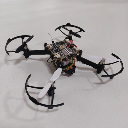
Pluto X
In this project, we used the PlutoX drone to achieve results such as collision avoidance, following a target and fetching sensor data mounted on top of the drone during aerial surveillance. The sensors used to achieve the above said behavior are the IR sensors (V53LOX) and analog sensors to determine the temperature and pressure when the drone is in flight mode.
Pluto Controller Android/ IOS App
The PlutoX drone comes with an android app ‘Pluto controller’. The android app provides the following functionalities:
- Calibrate the drift of the drone
- Calibrating accelerometer & magnetometer
- Drone Arming & take off
- Controlling the drone movement
- Flashing the drone with the firmware
- Developer mode
Installation
The android app is available on the playstore under the name Pluto Controller.
Calibrating Drift
In most of the cases, when you try to start the drone and fly it with/ without the android app the drone keeps drifting to one or two directions. To stabilize it, the drone drift needs to be calibrated. In the android app, it can be calibrated under the ‘Drone Settings’.
The drone works on three different axes as shown in the image below
- Roll
- Pitch
- Yaw
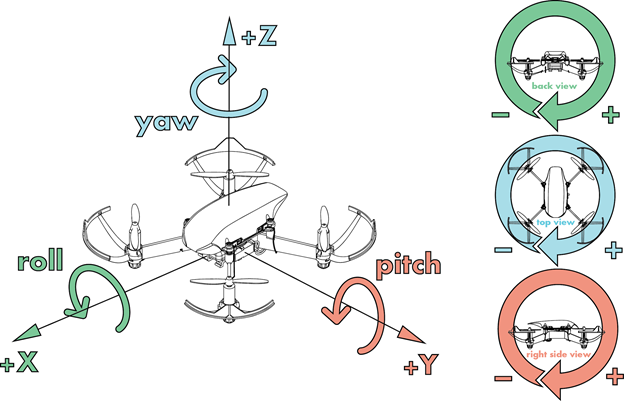
There are two parameters ‘Roll’ & ‘Pitch’ that can be changed to calibrate the drift. Refer to the below table:
| Drift Direction | Input set |
|---|---|
| forward | -ve pitch |
| backward | +ve pitch |
| left | -ve roll |
| right | +ve roll |
These settings can be calibrated in the ‘Drone Settings’ section of the app. It is advised to change the values in multiples on 5 first and then it can be calibrated more accurately after finding a upper limit.
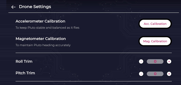
Calibrating Accelerometer & Magnetometer
In some cases, the drone does not fly properly & will keep moving in random directions. In such cases, the accelerometer and magnetometer have to be calibrated. While in other cases, the android app prompts to calibrate. These can be calibrated in the ‘Drone Settings’ section. For calibrating the accelerometer, ‘calibrate accelerometer’ button should be pressed & the drone has to be just placed on a flat surface. For calibrating the magnetometer, ‘calibrate accelerometer’ button should be pressed & the drone has to be rotated in all the three axis namely pitch, yaw and roll as shown in the ‘Calibrating Drift’ section.
Testing PlutoX connection
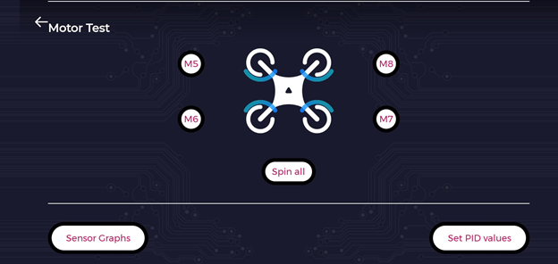
The connection to plutoX from the android app can be tested by running the propeller motors. In the ‘Drone Settings’ section, after scrolling down a bit, a model drone image can be seen. By clicking on each of the motors, the propeller connected to that motor can be spinned. All the motors can be run at the same time, by clicking on the ‘Spin all’ button. This feature is useful to verify connection with the drone.
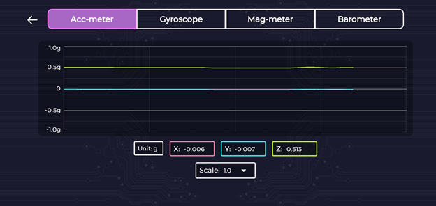
Sensor Graphs
The plutox has the following sensors on board (by default)
- Accelerometer
- Gyroscope
- Magnetometer
- Barometer
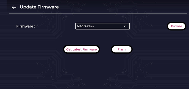
Flashing default firmware
At times when the drone is not functioning properly, or when there are issues with communication, or to reset the drone, it needs to flashed with the default firmware. The same can be achieved using the android app, from menu > Update Firmware. For the first time, by clicking on latest firmware the latest version for Pluto X will be downloaded from the web. Or if already downloaded, it can be browsed using the browse button. Once the firmware is selected (from the dropdown list), by clicking on Flash. This will sort of reset the drone with the original firmware. All the codes flashed on top of the default firmware will be erased by doing this.
CYGNUS IDE v1.0.6
Installation
To install the IDE required to program PlutoX, download the IDE from the link. Extract in the folder required and run ‘cygnus.exe’. There are binaries supported for Linux as well as Windows for this version.
Creating a Project
- Click on File -> New -> Pluto-X Project and enter the name of the project.
The resulting project folder is generated consisting of the libraries and the Makefile that is required by the project for compilation and flashing to the drone purposes.
The different functions that a PlutoX program has are as follows:
- void plutoInit()
- void onPilotStart()
- void plutoPilot()
- void onPilotFinish()

Functions
plutoInit()
This function is executed immediately after the drone powers up. This function is particularly useful for initializing hardware.
onPilotStart()
This function is executed once, after user the user turns the developer mode on. This function can be useful for initialising some variables
plutoPilot()
This function is executed in loop, along with drones internal primary stabilization code. By default this loop runs every 3.5ms. Using APIs, you can modify this loop frequency. This will not affect the drones internal stabilization loop.
onPilotFinish()
This function is executed once, after the user turns off the developer mode.
Building a Project
- Once the program is ready to be executed by the drone, the first step is to build the project which is just a basic compiling of the code.

- Click on the blue icon that will build and output any errors in the code. Once the code is built, a command prompt stating “Project Built Successfully” appears.

To flash the code to the PlutoX drone, follow the following steps:
- Ensure that the Android Application is not connected to the Drone.
- Connect your computer to the WiFi of the Drone’s SSID.
- Click on the ‘green’ link button on the top left to establish Pluto and Cygnus IDE connection (Chain will turn into red colour if connected). This is required to flash to the firmware of the drone.
- Once clicked, the color of the button turns to ‘red’ if it’s connected to the WiFi of the drone.
- After connecting Pluto WiFi to computer to flash the code select Flash command from toolbar. Flash command burn the code from the project you have selected or it burns the code from the project of current file opened in editor by default.
There are two categories of Flashing the device, namely:
- Full Flash: burn the code with erasing ROM data like accelerometer and magnetometer calibration.
- Normal Flash: burn code without erasing ROM data like sensor calibration.
It is recommended to use Full Flash when programming first time and make sure you calibrate accelerometer and magnetometer after Full Flash. Onwards you can use Normal Flash, If you observe any weird behaviour of Pluto after Normal Flash, prefer Full Flashing it again.
Running the code
- When you flash your program on Pluto it doesn’t directly starts executing, it’s in default mode. The User code execution starts when the drone is in developer mode. The developer mode can be controlled using the Pluto Controller app using the button </>. Please note that this button is accessible only when we choose “I am a Developer” from user profile in the App.

- To run your program you need to activate Developer Mode using Pluto Controller Android or iOS application.

- Once you have activated Developer Mode, the drone will execute the code running in the loop. When Developer Mode is deactivated, it will go back to its default mode.
The API documentation for v1.0.6 is available at this link.
Note - There are two different versions of CygnusIDE that we have worked on to support different functionalities. The reason for this is because the new firmware supports Breakout Board API functionalities regarding the ADC pins and the GPIO pins.The only difference between the two versions of Cygnus build are the function names and their implementations. The programs written with Cygnus v1.0.6 are not explained here, but are included on the github repository. The same programs are written with Cygnus v2.0.0 and they are included in the further section.
CYGNUS IDE v2.0.0
Installation
- To install the IDE required to program PlutoX, the new Cygnus build is available at the following link
- Extract in the folder required and run cygnus.exe. The installation is supported only on Windows.
The different functions that a PlutoX program in this build are
- plutoInit()
- onLoopStart()
- plutoLoop()
- onLoopStop()
The functionalities of these functions are same as that of the previous build. However, the implementation of the in-built functions are different. The API documentation for v2.0.0 is available here.
Note - There are two different versions of CygnusIDE that we have worked on to support different functionalities. The following code snippets are compatible with the new build of Cygnus which can be downloaded by the link shown above. (Cygnus 2.0 on Windows)
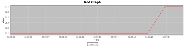
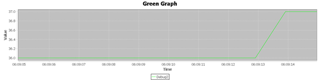
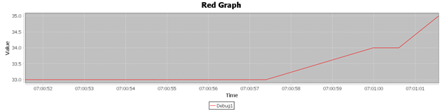
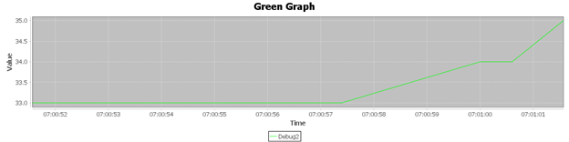
Monitoring Graphical Data
PlutoX has functions which can help monitor values of the sensors that come in-built such as the accelerometer on the IDE using the Pluto Monitor. At any given time, three graphs can be observed using the code.
Code
// Do not remove the include below
#include "PlutoPilot.h"
#include "Sensor.h"
#include "User.h"
#include "Utils.h"

//The setup function is called once at Pluto's hardware startup
void plutoInit()
{
// Add your hardware initialization code here
	setUserLoopFrequency(1000);
}

//The function is called once before plutoLoop when you activate Developer Mode
void onLoopStart()
{
 // do your one time stuff here
}

// The loop function is called in an endless loop
void plutoLoop()
{
//Add your repeated code here
	int32_t pressure, temp;
	pressure = Barometer.get(PRESSURE)/100;
	temp = Barometer.get(TEMPERATURE)/100 - 7;
	Monitor.println("Pressure " , pressure, 4);
	Monitor.println("Temperature " , temp, 4);
	Graph.red(pressure, 4);
	Graph.green(temp, 4);
}

//The function is called once after plutoLoop when you deactivate Developer Mode
void onLoopFinish()
{
// do your cleanup stuffs here
}
Results
Backflip Code
// Do not remove the include below
#include "PlutoPilot.h"
#include "XRanging.h"
#include "Utils.h"
#include "Peripheral.h"
#include "Sensor.h"
#include "User.h"
#include "Control.h"


Interval T2;
//The setup function is called once at Pluto's hardware startup
void plutoInit()
{
// Add your hardware initialization code here
}

//The function is called once before plutoPilot when you activate Developer Mode
void onLoopStart()
{
Command.takeOff(300);
	FlightMode.set(ATLTITUDEHOLD);
	T2.reset();
}

// The loop function is called in an endless loop
void plutoLoop()
{
//Add your repeated code here
	bool flag;
 flag = T2.set(2000,1);
	if(flag)
	{
		Command.flip(BACK_FLIP);
		Monitor.println("Flipping" );
	}
}
//The function is called once after plutoPilot when you deactivate Developer Mode
void onLoopFinish()
{
	 // do your cleanup stuffs here
}
Collision avoiding using X-Ranging Sensors
// Do not remove the include below
#include "PlutoPilot.h"
#include "XRanging.h"
#include "Utils.h"
#include "Peripheral.h"
#include "Sensor.h"
#include "User.h"
#include "Control.h"


Interval T2;
//The setup function is called once at Pluto's hardware startup
void plutoInit()
{
	XRanging.init(LEFT);
	XRanging.init(RIGHT);
}

//The function is called once before plutoPilot when you activate Developer Mode
void onLoopStart()
{
	Command.takeOff(250);
	FlightMode.set(ATLTITUDEHOLD);
}

// The loop function is called in an endless loop
void plutoLoop()
{
//Add your repeated code here
	int val = XRanging.getRange(LEFT);
	int val2 = XRanging.getRange(RIGHT);

	if(val >= 0 && val <= 200)
	{
		Monitor.println("LEFT ",val);
		RcCommand.set(RC_ROLL,1550);
	}

	if(val2 >= 0 && val2 <= 200)
	{
		Monitor.println("RIGHT ",val2);
		RcCommand.set(RC_ROLL,1450);
	}

	bool flag = T2.set(2000,1);
	if(flag){
		val = -100;
		RcCommand.set(RC_ROLL,1500);
	}
}

//The function is called once after plutoPilot when you deactivate Developer Mode
void onLoopFinish()
{
	 // do your cleanup stuffs here
//	 Xshield.stopRanging();
//	 Control.disableFlightStatus(false);
}
Following using X-Ranging Sensors
// Do not remove the include below
#include "PlutoPilot.h"
#include "XRanging.h"
#include "Utils.h"
#include "Peripheral.h"
#include "Sensor.h"
#include "User.h"
#include "Control.h"


Interval T2;
//The setup function is called once at Pluto's hardware startup
void plutoInit()
{
	XRanging.init(LEFT);
	XRanging.init(RIGHT);
// Add your hardware initialization code here
}

//The function is called once before plutoPilot when you activate Developer Mode
void onLoopStart()
{
	Command.takeOff(250);
	FlightMode.set(ATLTITUDEHOLD);
}

// The loop function is called in an endless loop
void plutoLoop()
{
//Add your repeated code here
	int val = XRanging.getRange(LEFT);
	int val2 = XRanging.getRange(RIGHT);

	if((val >= 100 && val <= 250) || (val2 > 10 && val2 < 80))
	{
		Monitor.println("LEFT ",val);
		RcCommand.set(RC_ROLL,1450);
	}

	if((val2 >= 100 && val2 <= 250) || (val > 10 && val < 80))
	{
		Monitor.println("RIGHT ",val2);
		RcCommand.set(RC_ROLL,1550);
	}


	bool flag = T2.set(2000,1);
	 if(flag){
	 val = -100;
	 RcCommand.set(RC_ROLL,1500);
	 }
}

//The function is called once after plutoPilot when you deactivate Developer Mode
void onLoopFinish()
{
	 // do your cleanup stuffs here
}
Components/Sensors
X-Ranging
This API is required to access the X-ranging Shield. The functions that come along with this API are as follows:
- void init() : Initializes all the four sensors i.e., FRONT, BACK, LEFT, RIGHT.
- void init(laser_e laser) : Initializes any one of the mentioned sensors among the following from FRONT, BACK, LEFT, RIGHT.
- int16_t getRange(laser_e laser) : Instantaneous range from a particular sensor where laser can be any one of the following from FRONT, BACK, LEFT, RIGHT.

The IR sensor consists of 5 connections namely VCC, GND, RESET, I2C pins SCL and SDA. The breakout board provides I2C connections. Getting range from IR sensors is done by using Xshield API.
X-Breakout
X-Breakout is an add-on shield using which any external sensor can be integrated with PlutoX. It has special slots/ports provided for UART, I2C, SPI, ADC/DAC, PWM which can be used directly to integrate any external modules. All the 20 unibus pinouts are accessible through X-Breakout and also 20 general purpose pinouts are available.
More details about the board can be found here.
Problems
Over the course of the project, we encountered various types of problems with the drone. We are listing out the problems and solutions we know of, so that it helps anyone working on this in the future.
Sensors
When couldn’t interface digital sensors (say DHT11), on to the drone using the X-breakout board. The program to read data from DHT11 required interval/ clock function, i.e to able to read data after a given interval. These functions were available for both of the Cygnus versions, but we weren’t aware of them initially and what are these functions. Later on, we found out that the functions millis() and micros() can be used for this purpose, to program. Besides this, due to lack of proper resources we couldn’t interface the analog sensors on the old Cygnus. Only after contacting the Pluto technical support, we were told that there were problem with the old IDE and there is a newer version, that support reading analog values. By following the existing libraries of the sensors for arduino or related boards, the code can be ported on to the drone.
Apart from the API issues, there were also connecting issues with the sensors. There are exact jumper pins on the breakout board to connect the sensors. When we were able to get data from the sensor with the drone disarmed, we wanted to get data when the drone is being flown around. For this, we wanted to solder the sensor on the board. When we soldered, because of the soldered blob being a little big and because the breakout board is a 2-sided board, when we tried to connect the board after soldering, the drone malfunctioned and the breakout board slot on the board and on the drone got burnt a little bit. The drone kept spinning it’s fans the moment it was switched on since then. After getting in touch, with the technical support we were asked to short a resistor, we were able to get the board working again. We are not sure if it soldering error for sure, but it seems so.
Try the following solution:
- Unscrew the flight controller PrimusX from the drone frame.
- Check back part of PrimusX

- Remove the marked resistor as shown in the above picture and short it using solder as shown in the below picture.


Camera API
Going by the initial plan of trying to make the drone do image processing and follow a particular object, even though the camera module was available and the camera feed was accessible through the android app, we weren’t able to get the feed through ROS or through cygnus.
If we would’ve got the feed through ROS, we can send the feed to the system on which roscore is running, do the required image processing, detect the object, find the direction and distance, and then using ROS drone can be commanded to move in that direction for the given distance. This keeps running in a loop, feed is sent by ROS node on drone, to the core system, where image processing is done and the command to move is given back to the node. The support for camera feed was still in development and wasn’t available over the course of the project. The beta version of the support for camera feed on ROS was made available by the company a few days back (i.e few days before the final demo). Therefore, we couldn’t work on the camera as planned initially. The Camera API ros package sent to us can be found here.
Cygnus versions
Since we were working with different Cygnus versions, the usage of APIs is different in both of them. Although there are separate documentations for both the versions, we faced difficulty to understand and use the APIs. For the same, besides following the API documentation we had to look into the header files present in project_folder > platform. By looking into the header files the return types, input parameter types and enum types defined are useful when using the APIs.
Conclusion
Since the PlutoX drone is still in development, we had to face a lot of problems over the course of the project. Besides this, we were able to get basic functionalities of the drone working. The support for ROS, make it great to execute real time functionalities by sending data from drone to a remote node. The camera feed support which was released can be used to run image processing while the drone is in the air. If the right set of jumper pins/ if the sensors are properly soldered on to the drone, data can be retrieved from the drone when it is being flown around. The drone API is really great and it supports controlling motors, direction, speed, etc. Apart from all the bugs and lack of docs, overall PlutoX drone is a great platform to learn and program drones. We tried our best to include all the required details in this documentation, and we also included all the resources we have come across so that it makes it easier for anyone continuing this project.